The Transformation Pipeline
Build a complete 3D graphics pipeline from scratch. Transform vertices from local space to screen space using matrices and homogenous coordinates.
In the previous lessons, we learned the theory behind and how to use the to create them. Now, we are going to put it all together.
We are going to build a basic graphics pipeline. This is a sequence of mathematical operations that takes raw 3D data (vertices) and transforms them, step-by-step, until they land on specific pixels on your 2D screen.
We will start with a simple triangle defined in 3D space. We'll get it on screen immediately using a basic implementation, and then we will progressively upgrade our code to implement the model, view, and projection transformations required to render it correctly with 3D perspective.
Starting Point
We will start with a clean project structure similar to our previous examples. We have a main.cpp handling the loop and a Window class handling the SDL window.
We also have a Scene class. This will manage our objects and eventually our camera logic. Note that Scene::Render accepts an SDL_Surface*. This is the surface of the window we want to draw onto.
Files
Defining Geometry (Local Space)
In 3D graphics, shapes are defined by vertices (points in 3D space). A triangle is the simplest polygon, requiring just three vertices.
Artists create and export these assets with vertices defined in local space (sometimes called object space). This means the coordinates are relative to the object itself, not the world.
Let's create a Triangle class to represent a simple 3D asset. It will hold a std::vector of glm::vec3 points. We will define a triangle whose local space is centered at (0,0,0), with 3 vertices scattered around that origin.
We can use any values we want here, but following example represents an triangle where each side has a length of approximately 1.0:
src/Triangle.h
#pragma once
#include <vector>
#include <SDL3/SDL.h>
#include <glm/glm.hpp>
class Triangle {
public:
Triangle() {
// Define vertices in Local Space
// (Relative to the center of the triangle)
Vertices = {
{0.0f, -0.577f, 0.0f}, // Bottom
{0.5f, 0.289f, 0.0f}, // Top Right
{-0.5f, 0.289f, 0.0f} // Top Left
};
}
void HandleEvent(SDL_Event& Event) {}
void Tick(float DeltaTime) {}
void Render(SDL_Surface* Surface) {}
private:
std::vector<glm::vec3> Vertices;
};We'll also update our Scene to include a Triangle:
src/Scene.h
#pragma once
#include <vector>
#include <SDL3/SDL.h>
#include "Triangle.h"
class Scene {
public:
Scene() {
// Add a single triangle to the scene
Triangles.emplace_back();
}
void HandleEvent(SDL_Event& Event) {
for (auto& Tri : Triangles) {
Tri.HandleEvent(Event);
}
}
void Tick(float DeltaTime) {
for (auto& Tri : Triangles) {
Tri.Tick(DeltaTime);
}
}
void Render(SDL_Surface* Surface) {
for (auto& Tri : Triangles) {
Tri.Render(Surface);
}
}
private:
std::vector<Triangle> Triangles;
};Drawing Vertices
Before we get into matrix math, let's just try to get these dots on the screen by implementing Triangle::Render().
Our vertices are currently at coordinates like (0.0, 0.5) and (0.5, -0.5). The surface we're rendering on uses pixels, where (0,0) is the top-left and, given the dimensions of the window in our example, (700, 300) is the bottom-right.
For now, let's just write a DrawVertex() function that scales our triangle up by a factor of 100, and moves it to the center of the screen.
This is also where we'll deal with the y-axis mismatch, where our local space and world space uses y-up, but the SDL_Surface uses y-down. We'll handle this simply by scaling the y positions of our vertices by -100 instead of 100:
src/Triangle.h
// ...
class Triangle {
public:
// ...
void Render(SDL_Surface* Surface) {
for (const glm::vec3& LocalVertex : Vertices) {
DrawVertex(Surface, LocalVertex);
}
}
private:
void DrawVertex(
SDL_Surface* Surface, const glm::vec3& Vertex
) {
// Position
float ScreenW{float(Surface->w)};
float ScreenH{float(Surface->h)};
float ScreenX{(Vertex.x * 100.0f) + (ScreenW * 0.5f)};
float ScreenY{(Vertex.y * -100.0f) + (ScreenH * 0.5f)};
// Color
const auto* Fmt{
SDL_GetPixelFormatDetails(Surface->format)
};
Uint32 Color{SDL_MapRGB(Fmt, nullptr, 255, 0, 0)};
// Draw
SDL_Rect PixelRect{
int(ScreenX) - 5,
int(ScreenY) - 5,
10, 10
};
SDL_FillSurfaceRect(Surface, &PixelRect, Color);
}
std::vector<glm::vec3> Vertices;
};We will revisit this function in the next lesson when we fully implement view space and screen space but, for now, it just lets us get something on the screen.
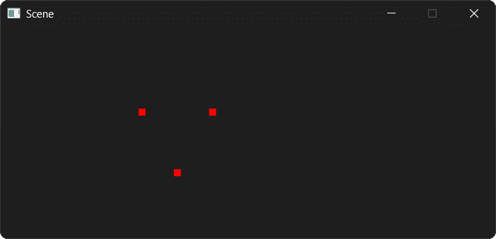
If you run the application now, you should see three red dots representing the verticies of our triangle in the center of the window:

The Model Matrix (World Space)
The manual offset we just wrote is extremely limiting. We can't easily rotate the object or move it to a specific 3D coordinate. This is where the pipeline begins.
The first transformation moves an object from Local Space to World Space. We call this the Model Matrix. Let's use GLM to build and use this model matrix inside our Render() function.
We're working in 3D space and we want to use affine transformations with homogenous coordinates, so we'll use a 4x4 matrix. We start with an identity matrix:
This starting point represents no transformation at all, but we can add to it later. We can create this matrix by passing 1.0f to a glm::mat4 constructor:
glm::mat4 Model{1.0f};Next, we add the homogenous coordinate to our vertex. The glm::vec4 type makes this easy as it has a constructor that accepts a glm::vec3, as the first argument, and the value as the second. Since our vertices represent positions, we want them to be affected by translation, so we set :
// LocalVertex is a glm::vec3
glm::vec4{LocalVertex, 1.0f};We then use matrix multiplication to transform the glm::vec3 using our 4x4 matrix. As GLM uses a column-major format, the transformation matrix is the left side of the multiplication, whilst the vector is on the right.
Model * glm::vec4{LocalVertex, 1.0f};We finally provide RenderVertex() with our transformed (world-space) vertex rather than the local vertex. This new vertex is a glm::vec4, so we need to update our argument list, but the function body remains the same for now. Our complete code looks like this:
src/Triangle.h
// ...
class Triangle {
public:
// ...
void Render(SDL_Surface* Surface) {
// Create our transformation as an identity matrix
glm::mat4 Model{1.0f};
// We'll implement transformations here in the next section
// ...
for (const glm::vec3& LocalVertex : Vertices) {
// Implement the transformation
glm::vec4 WorldVertex{
// - matrix on the left, vertex on the right
// - vertex is updated to a vec4, with w=1
Model * glm::vec4{LocalVertex, 1.0f}
};
// Provide the transformed vertex
DrawVertex(Surface, LocalVertex);
DrawVertex(Surface, WorldVertex);
}
}
private:
void DrawVertex(
SDL_Surface* Surface, const glm::vec3& Vertex
SDL_Surface* Surface, const glm::vec4& Vertex
) {
// ... function body unchanged
}
// ...
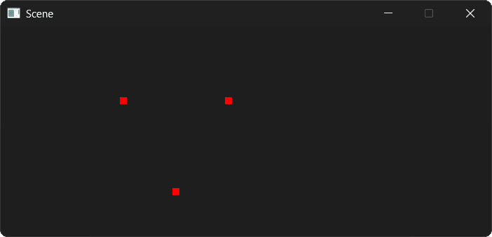
};If you run the app now, we should see everything looks the same, but we're now ready to start implementing transformations:
Implementing Transformations
To make creating transformation matrices easier, GLM provides a collection of helpful utilities, with names like translate(), rotate(), and scale().
These are available within the glm/ext/matrix_transform.hpp header. These functions take the matrix we want to update as the first argument, followed by additional arguments depending on the transformation type.
Translation
The glm::translate() function takes the matrix we want to update as the first argument, and a glm::vec3 representing the translation as the second argument.
In the following example, we translate our triangle into the location represented by a glm::vec3 called Position.
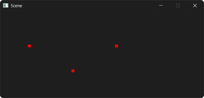
We've set to move our triangle 1 unit in the negative direction within world space:
src/Triangle.h
// ...
#include <glm/ext/matrix_transform.hpp>
class Triangle {
public:
// ...
void Render(SDL_Surface* Surface) {
glm::mat4 Model{1.0f};
// Move the triangle to Position
Model = glm::translate(Model, Position);
// ...
}
private:
// ...
glm::vec3 Position{-1.0f, 0.0f, 0.0f};
};Our current DrawVertex() function converts this to a 100 pixel leftward movement in screen space:
Scale
The glm::scale() function accepts the matrix to update as the first argument, and a glm::vec3 representing the scale in each dimension as the second argument.
The glm::vec3 type can be constructed with a single floating point argument, which sets every component to that value. Below, we use this to make our triangle 50% bigger:
src/Triangle.h
// ...
class Triangle {
public:
// ...
void Render(SDL_Surface* Surface) {
glm::mat4 Model{1.0f};
Model = glm::translate(Model, Position);
Model = glm::scale(Model, glm::vec3{1.5f});
// ...
}
// ..
};We still have our glm::translate() call, so our Model matrix contains both the translation and the scaling:
In this example, we apply a non-uniform scaling, stretching the triangle by a factor of 3 in the x dimension, but keeping its height and depth the same:
src/Triangle.h
// ...
class Triangle {
public:
// ...
void Render(SDL_Surface* Surface) {
glm::mat4 Model{1.0f};
Model = glm::translate(Model, Position);
Model = glm::scale(Model, glm::vec3{3.0f, 1.0f, 1.0f});
// ...
}
// ..
};
Rotation
Finally, we have glm::rotate() for rotation. 3D rotation is a little more complex than 2D rotations. In addition to how much we want the object rotated, we also need to provide the axis of that rotation.
To support this, glm::rotate() accepts three arguments:
- The matrix to apply the transformation to
- The angle of rotation, expressed in radians. We can use
glm::radians()to convert from degrees to radians, andglm::degrees()to convert from radians to degrees. - The axis of rotation, expressed as a
glm::vec3
Below, we add a 90 degree rotation to our triangle. We use as the axis of rotation, meaning the z components of our vectors will remain fixed. The rotation will be implemented by updating the x and y coordinates.
src/Triangle.h
// ...
class Triangle {
public:
// ...
void Render(SDL_Surface* Surface) {
glm::mat4 Model{1.0f};
Model = glm::translate(Model, Position);
Model = glm::scale(Model, glm::vec3{3.0f, 1.0f, 1.0f});
Model = glm::rotate(
Model,
glm::radians(90.0f),
glm::vec3{0.0f, 0.0f, 1.0f}
);
// ...
}
// ..
};This transformation is effectively a 2D rotation in our current scene, as the x and y coordinates of our vertices are mapping to the x and -y axes of our SDL_Surface:
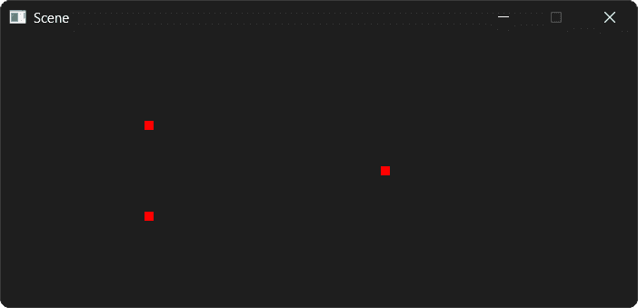
We're currently ignoring z, but we'll start using it in the next lesson when we implement depth within our scene.
Dynamic Transformations
Our scene is currently static, but we can modify our transformations using all the usual C++ techniques.
In the following example, we update our triangle's position using the arrow keys, its scale using the mouse wheel, and we animate it by updating its rotation on every Tick():
src/Triangle.h
// ...
class Triangle {
public:
// ...
void HandleEvent(SDL_Event& Event) {
if (Event.type == SDL_EVENT_KEY_DOWN) {
switch (Event.key.key) {
case SDLK_LEFT: Position.x -= 0.1f; break;
case SDLK_RIGHT: Position.x += 0.1f; break;
case SDLK_UP: Position.y += 0.1f; break;
case SDLK_DOWN: Position.y -= 0.1f; break;
}
} else if (Event.type == SDL_EVENT_MOUSE_WHEEL) {
if (Event.wheel.y > 0) Scale += 0.1f;
if (Event.wheel.y < 0) Scale -= 0.1f;
}
}
void Tick(float DeltaTime) {
Rotation += 90.0f * DeltaTime;
}
void Render(SDL_Surface* Surface) {
glm::mat4 Model{1.0f};
Model = glm::translate(Model, Position);
Model = glm::scale(Model, glm::vec3{Scale});
Model = glm::rotate(
Model,
glm::radians(Rotation),
glm::vec3{0.0f, 0.0f, 1.0f}
);
// ...
}
private:
// ...
float Scale{1.5f};
float Rotation{90.0f}; // Degrees
};Complete Code
Our ending point is provided in full below. We'll continue to build on this in the next lesson to implement depth and a virtual camera:
Files
Summary
In this lesson, we started building a full graphics pipeline from scratch.
- Local Space: We defined vertices relative to the object itself.
- World Space: We used a model matrix to move, scale, and rotate the object in the world.
- Matrix Construction: We used GLM's translate, scale, and rotate functions to build our model matrix
- Matrix Multiplication: We transformed our local space vectors to world space vectors by multiplying them by our model matrix
In the next lesson, we'll continue our journey through the graphics pipeline. We'll introduce a view matrix to implement a virtual camera, and a projection matrix to give our scene 3D perspective.
View and Projection Matrices
Complete the 3D graphics pipeline by implementing View and Projection matrices. Learn about camera simulation, perspective projection, and the viewport transform.