View and Projection Matrices
Complete the 3D graphics pipeline by implementing View and Projection matrices. Learn about camera simulation, perspective projection, and the viewport transform.
In the previous lesson, we began building our 3D graphics pipeline. We successfully moved our triangle from local space (vertices relative to the object's center) to world space (vertices relative to the center of the world) using a model matrix.
However, our current rendering has two major limitations:
- We have no concept of a "camera." We are simply drawing objects based on their absolute position in the world. To view the world from different angles, we need a view matrix.
- We have no depth perception. Objects further away look the same size as objects close up. To simulate 3D depth on a 2D screen, we need a projection matrix.
In this lesson, we will complete the transformation pipeline. We will implement a virtual camera using glm::lookAt(), simulate 3D perspective using glm::perspective(), and finally learn how to correctly map these 3D coordinates to the 2D pixels on our screen using the perspective divide and viewport transform.
The MVP Pipeline
Standard real-time rendering pipelines rely on three key matrices to transform a vertex from its raw data state to a position on your screen. These are often collectively referred to as the MVP (Model-View-Projection) matrices.
- Model Matrix: Transforms from local space to world space. This handles the position, rotation, and scale of individual objects. We implemented this in the previous lesson.
- View Matrix: Transforms from world space to view space. This reorients the entire world so that it aligns with the camera's point of view.
- Projection Matrix: Transforms from view space to clip space. This handles the camera's lens properties (like field of view) and prepares the data for perspective effects.
Once we have our coordinates in clip space, we perform two final automatic steps (perspective divide and viewport transform) to get the final pixel coordinates for our SDL_Surface.
Starting Point
We will continue directly from where we left off. We have a Triangle class that holds vertices and manages its own model matrix, a Window class for rendering, and a Scene class that orchestrates the update loop.
Files
The View Matrix (Camera)
Currently, we are viewing our world from a fixed, hard-coded perspective. If we want to move the camera to the left, we would have to move every single object in the world to the right to create that illusion.
As we discussed in our earlier lesson, this is exactly what the view matrix does. It transforms coordinates from world space to view space. In view space, the camera is always at the origin , whilst the world moves around it.
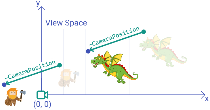
In our earlier lesson, we were only working in a 2D world, and we only supported camera translation, not rotation. We implemented this transformation by moving objects in the opposite direction to our camera's position in world space:
In 3D, this backwards transform of moving the world around a camera is even more difficult to conceptualize, especially if we also want to support camera rotation along each possible axis.
Fortunately, GLM provides a function that makes this easier. The glm::lookAt() function lets us create our view matrix by thinking exactly like a human does.
Using glm::lookAt()
The glm::lookAt() function constructs a view matrix based on three parameters:
- Where is the camera positioned in the world?
- What position in the world is the camera looking at?
- Which direction is "up" for the camera?
Each argument is a glm::vec3, and this image visualizes what they mean:
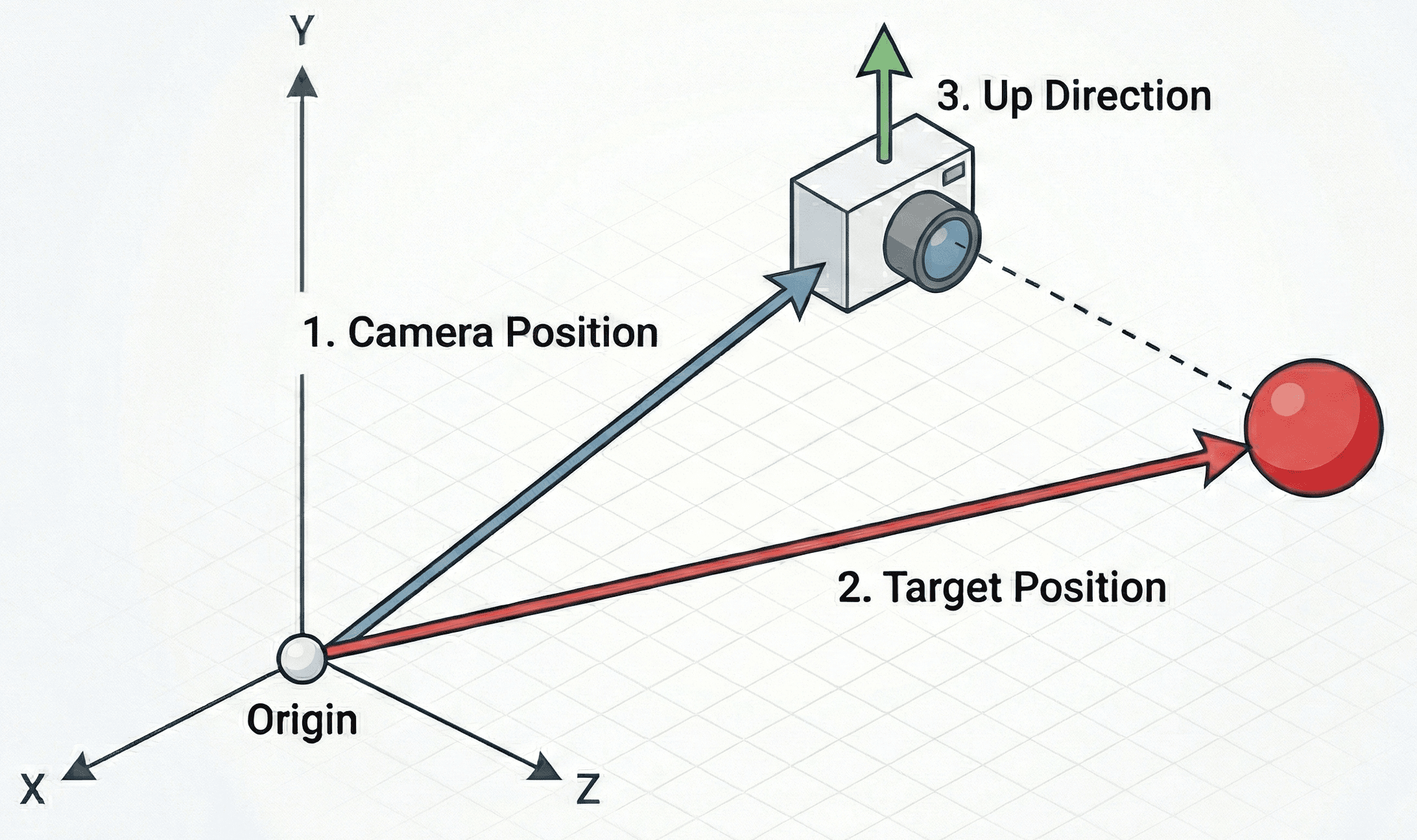
The third argument is usually the most confusing. Most commonly, we just want our camera to be oriented in the same way someone typically holds a camera in the real world. This means the "up" direction for the camera is exactly the same as the "up" direction of the world. In our case, and in most cases, that is positive y: .
Let's imagine we want to place our camera at (0, 0, 3) (3 units back from the origin), looking at the origin (0, 0, 0), with (0, 1, 0) being "up" (standard Y-up orientation).
We can generate this matrix like this:
glm::vec3 CameraPos{0.0f, 0.0f, 3.0f};
glm::vec3 Target{0.0f, 0.0f, 0.0f};
glm::vec3 Up{0.0f, 1.0f, 0.0f};
glm::mat4 View{glm::lookAt(CameraPos, Target, Up)};Let's integrate this into our Triangle class. We will add a CameraPosition member variable so we can move it later, and update Render() to apply the view transformation.
We are applying this transformation after the Model transformation but, in column-major matrix multiplication, we read right-to-left. This means we multiply the vertex by the model matrix, and then multiply that result by the view matrix:
Or simply:
Let's update Scene.h to store a CameraPosition, and use it to calculate a View matrix which we'll use when rendering all of our Triangle instances:
src/Scene.h
#pragma once
#include <vector>
#include <SDL3/SDL.h>
#include <glm/glm.hpp>
#include <glm/ext/matrix_transform.hpp>
#include "Triangle.h"
class Scene {
public:
Scene() {
// Add a single triangle to the scene
Triangles.emplace_back();
}
void HandleEvent(SDL_Event& Event) {
for (auto& Tri : Triangles) {
Tri.HandleEvent(Event);
}
}
void Tick(float DeltaTime) {
for (auto& Tri : Triangles) {
Tri.Tick(DeltaTime);
}
}
void Render(SDL_Surface* Surface) {
glm::mat4 View{glm::lookAt(
CameraPosition,
glm::vec3{0.0f, 0.0f, 0.0f},
glm::vec3{0.0f, 1.0f, 0.0f}
)};
for (auto& Tri : Triangles) {
Tri.Render(Surface, View);
}
}
private:
std::vector<Triangle> Triangles;
glm::vec3 CameraPosition{0.0f, 0.0f, 5.0f};
};We'll update Triangle.h to receive this matrix and use it to transform its vertices as part of the rendering pipeline:
src/Triangle.h
// ...
class Triangle {
public:
// ...
void Render(
SDL_Surface* Surface, const glm::mat4& View
) {
glm::mat4 Model{1.0f};
Model = glm::translate(Model, Position);
Model = glm::scale(Model, glm::vec3{Scale});
Model = glm::rotate(
Model,
glm::radians(Rotation),
glm::vec3{0.0f, 0.0f, 1.0f}
);
for (const glm::vec3& LocalVertex : Vertices) {
// Apply Model then View transform
glm::vec4 ViewVertex{
View * Model * glm::vec4{LocalVertex, 1.0f}
};
DrawVertex(Surface, ViewVertex);
}
}
// ...
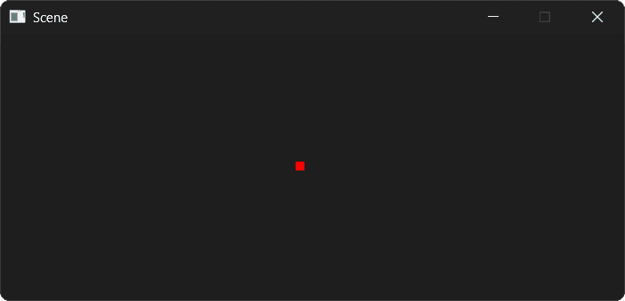
};Our scene should continue to render as it did before.
Our virtual camera is still looking along the z-axis, from its CameraPosition at to the target position of .
Freeform Cameras
The glm::lookAt() function is helpful when we want to control what our camera is looking at, but for a freeform camera, we need to remove this restriction.
Just like our Model matrix, our View matrix can be created by composing functions like glm::translate() and glm::rotate().
For camera translation, we translate the world in the opposite direction to the camera's position, as we covered previously:
// ...
class Scene {
public:
void Render(SDL_Surface* Surface) {
// Start with an identity matrix as usual
glm::mat4 View{1.0f};
// Apply camera position (translation)
View = glm::translate(View, -CameraPosition);
for (auto& Tri : Triangles) {
Tri.Render(Surface, View);
}
}
// ...
};For a full 3D rotation, we need to control the rotation along each of the 3 axis. These three rotations are generally called pitch, yaw, and roll.
Let's add 3 variables for them, and then compose 3 rotations into our matrix using glm::rotate(). Remember, our view transformation isn't really moving the camera around the world - it is moving the world around the camera. We use negative values to rotate things in the opposite direction:
// ...
class Scene {
public:
// ...
void Render(SDL_Surface* Surface) {
glm::mat4 View{1.0f};
// Roll around Z-axis
View = glm::rotate(
View, -CameraRoll, glm::vec3{0.0f, 0.0f, 1.0f}
);
// Pitch around X-axis
View = glm::rotate(
View, -CameraPitch, glm::vec3{1.0f, 0.0f, 0.0f}
);
// Yaw around Y-axis
View = glm::rotate(
View, -CameraYaw, glm::vec3{0.0f, 1.0f, 0.0f}
);
View = glm::translate(View, -CameraPosition);
for (auto& Tri : Triangles) {
Tri.Render(Surface, View);
}
}
private:
// ...
// Rotation around X-axis (up/down)
float CameraPitch{0.0f};
// Rotation around Y-axis (left/right)
float CameraYaw{0.0f};
// Rotation around z-axis (rolling)
float CameraRoll{0.0f};
};Again, our scene should continue to render as it did before:
However, we now have more fine grained control over our camera. Let's make it interactive by modifying these variables in response to input.
Interactive Cameras
Let's update HandleEvent() to control the camera's rotation and position, instead of the triangle's position:
Files
Running our scene, we can now rotate the camera using the arrow keys, and move it forward and back using the mouse wheel.
There are two problems remaining:
- We're ignoring depth - moving our camera forward or back does not make our triangle larger or smaller
- We're rendering things that are behind the camera. We can see this when we rotate our camera approximately 180 degrees, at which point the triangle will be projected onto our screen from behind the camera
We'll fix both of these in the next two sections.
The Projection Matrix (Clip Space)
The view matrix aligns the world to the camera, but it doesn't handle perspective. In the real world (and in photos), parallel lines appear to converge as they get further away, and objects get smaller as their distance from the viewer increases.
This is the job of the projection matrix. It transforms view space into clip space.
Clip Space gets its name because it is the space where geometry is "clipped" (discarded) if it falls outside the camera's visible range. This visible volume is called the frustum.
A perspective frustum looks like a pyramid with the top cut off:
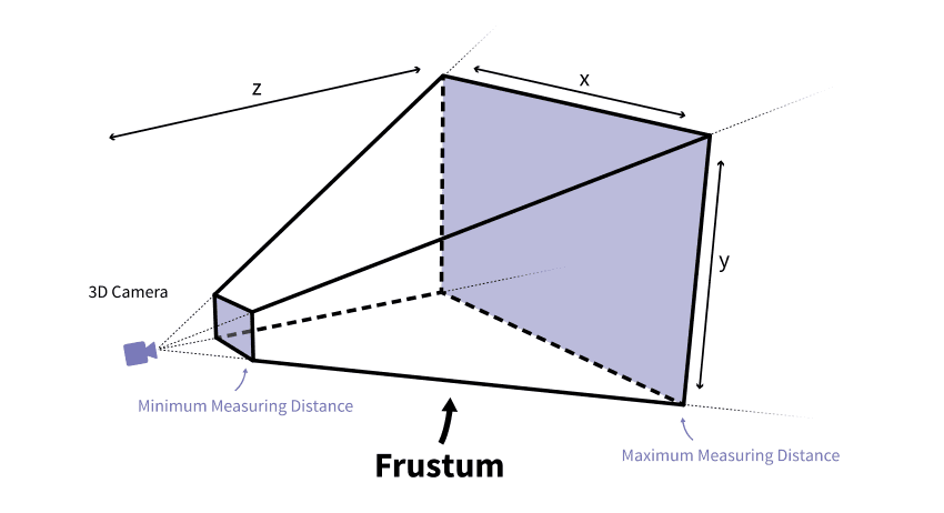
Image Source: Jakob Killian
Again, this is fairly complex matrix to conceptualize but, to make things easier, GLM provides glm::perspective(). It takes four parameters where we define the shape of the frustrum, which it uses to create the corresponding matrix behind the scenes:
- FOV (Field of View): The vertical angle of the camera's view (in radians). A typical value is 45 degrees -
glm::radians(45.0f). - Aspect Ratio: The width of the viewport divided by the height. This ensures the image isn't squashed or stretched.
- Near Plane: The distance to the closest point the camera can see. Objects closer than this are clipped.
- Far Plane: The distance to the furthest point the camera can see. Objects further than this are clipped.
All values are floating point numbers, and the ideal near/far plane values depend heavily on the type of scene we're rendering. They tend to be set by experimentation and tuning to find values that minimize rendering artifacts.
Using glm::perspective()
We need to include the glm/ext/matrix_clip_space.hpp header to access this function.
Let's add the projection matrix to Triangle::Render(). We will construct it using the window's dimensions for the aspect ratio.
Finally, we use matrix multiplication to combine both of our View and Projection functions into a single transformation matrix:
src/Triangle.h
// ...
#include <glm/ext/matrix_clip_space.hpp>
class Scene {
public:
// ...
void Render(SDL_Surface* Surface) {
glm::mat4 View{1.0f};
View = glm::rotate(
View, -CameraRoll, glm::vec3{0.0f, 0.0f, 1.0f}
);
View = glm::rotate(
View, -CameraPitch, glm::vec3{1.0f, 0.0f, 0.0f}
);
View = glm::rotate(
View, -CameraYaw, glm::vec3{0.0f, 1.0f, 0.0f}
);
View = glm::translate(View, -CameraPosition);
float AspectRatio{
float(Surface->w) / float(Surface->h)
};
glm::mat4 Projection{glm::perspective(
glm::radians(45.0f), // 45 degree FOV
AspectRatio,
0.1f, // Near plane
100.0f // Far plane
)};
for (auto& Tri : Triangles) {
// Combine the projection and view transforms
// Order matters - the projection is the left
// operand, and view is the right
Tri.Render(Surface, View);
Tri.Render(Surface, Projection * View);
}
}
// ...
};As a reminder, within Tri.Render(), we're multiplying the vertex by the model matrix, and then by this Projection * View argument.
So, our transformation is: Vertex Model View Projection
However, our column-major matrix multiplication is read right-to-left, so the actual expression is:
Projection * View * Model * VertexWe now have our vertex in clip space. But if we pass this directly to our old DrawVertex() function, it won't work correctly.
We need to rewrite this into a proper viewport transformation function that handles the unique properties of clip space coordinates.
The Perspective Divide (NDC)
In clip space, the coordinate system is a bit unusual. It is a 4D homogeneous coordinate system ().
The projection matrix multiplication has done something magic: it has stored the vertex's original depth (its distance from the camera) into the component.
To get the perspective effect - where things get smaller as (depth) increases - we must divide the , , and components by .
This operation is called the perspective divide. Let's replace DrawVertex() with our new implementation, and start by performing this divide.
Note that there's a possibility that we will be dividing by zero here - we fix this problem in the next section:
src/Triangle.h
// ...
class Triangle {
// ...
private:
void DrawVertex(
SDL_Surface* Surface, const glm::vec4& ClipVertex
) {
// 1. Perspective Divide (Clip Space -> NDC)
// TODO: Prevent division by zero
glm::vec3 NDC{
ClipVertex.x / ClipVertex.w,
ClipVertex.y / ClipVertex.w,
ClipVertex.z / ClipVertex.w
};
}
// ...
};The result is a coordinate in normalized device coordinates (NDC). In OpenGL (and GLM's default configuration), NDC space is a cube where , , and all range from -1.0 to 1.0.
- is the left edge of the screen.
- is the right edge.
- is the bottom edge.
- is the top edge.
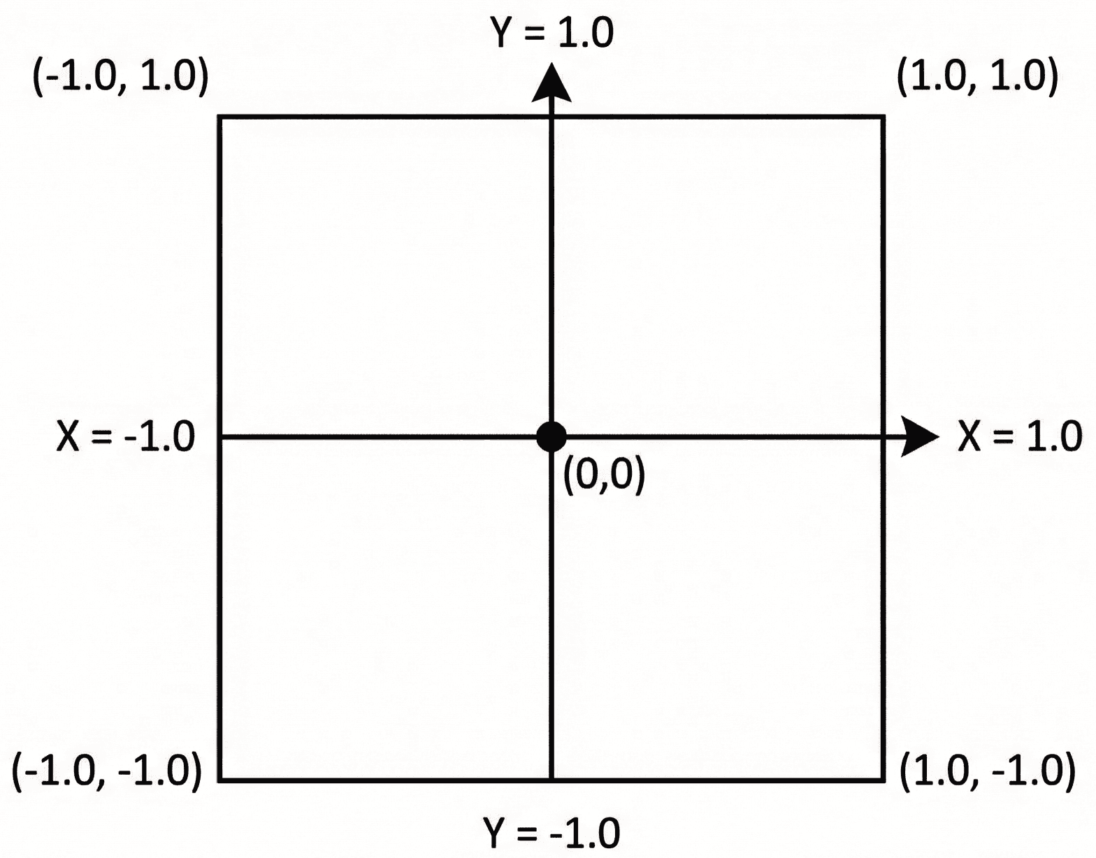
Our z component is also updated with the depth of the vertex, should we need it. Our near plane is positioned at in this space, whilst is the far plane. Anything inside this -1 to 1 cube is considered "visible" to our camera. Anything outside is not in the camera's view.
If we were using a typical hardware-accelerated pipeline, content outside of this cube would be discarded (or "clipped") at this stage, and no longer be considered when processing this frame.
Alternative Perspective Functions
The default glm::perspective() function makes two assumptions:
- Our view space is set up such that is "forward" - that is, our camera is facing the negative z direction.
- We want the depth in NDC to range from
-1(near plane) to+1(far plane)
These are valid assumptions if we were using our matrices with the OpenGL API, but not for others.
Most other APIs use an NDC ranges from 0 (near plane) to 1 (far plane). Additionally, we may want to define our view such that camera is looking in the positive z direction.
Alternative versions of glm::perspective() are available to accommodate these different requirements:
// Matrix that transforms a left handed (+z is
// "forward") view, setting z depth from 0 to 1
glm::mat4 P1{
glm::perspectiveLH_ZO(fovy, aspect, near, far)
};
// Matrix that transforms a right handed (-z is
// "forward") view, setting z depth from 0 to 1
glm::mat4 P2{
glm::perspectiveRH_ZO(fovy, aspect, near, far)
};
// Matrix that transforms a left handed (+z is
// "forward") view, setting z depth from -1 to 1
glm::mat4 P3{
glm::perspectiveLH_NO(fovy, aspect, near, far)
};
// Matrix that transforms a right handed (-z is
// "forward") view, setting z depth from -1 to 1
glm::mat4 P4{
glm::perspectiveRH_NO(fovy, aspect, near, far)
};The glm::perspectiveRH_NO() function is equivalent to the default glm::perspective() - it just uses a more explicit name.
The Viewport Transform
The final step is mapping these NDC coordinates (-1 to 1) to actual pixel coordinates (e.g., 0 to 700). This is the viewport transform.
One way of doing this is the following process:
- Shift the range from
[-1, 1]to[0, 2]by adding 1. - Scale the range from
[0, 2]to[0, 1]by dividing by 2. - Scale
[0, 1]to the window dimensions (e.g.,[0, 700]).
For the Y-axis, we have the usual problem: our space uses y-up, but SDL_Surface uses y-down. So again, we need to invert the Y axis during this transform:
src/Triangle.h
// ...
class Triangle {
// ...
private:
void DrawVertex(
SDL_Surface* Surface, const glm::vec4& ClipVertex
) {
// 1. Perspective Divide
// TODO: Prevent division by zero
glm::vec3 NDC{
ClipVertex.x / ClipVertex.w,
ClipVertex.y / ClipVertex.w,
ClipVertex.z / ClipVertex.w
};
// 2. Viewport Transform (NDC -> Screen Space)
float ScreenW{float(Surface->w)};
float ScreenH{float(Surface->h)};
// Map X from [-1, 1] to [0, Width]
float ScreenX{
(NDC.x + 1.0f) * 0.5f * ScreenW
};
// Map Y from [-1, 1] to [0, Height]
// Note the (1.0 - NDC.y) term here. This flips
// the Y axis because SDL's 0 is at the top,
// but GLM's +1 is at the top.
float ScreenY{
(1.0f - NDC.y) * 0.5f * ScreenH
};
}
// ...
};Finally, let's draw our points. SDL will automatically ignore attempts to draw outside of the SDL_Surface bounds.
However, we need to handle situations where the vertex is within the bounds, but where it is behind the camera.
After the perspective divide, any vertex behind the camera will have a negative component, so we check if (ClipVertex.w <= 0) before rendering.
We're using <= instead of < because we also want skip vertices whose component is exactly 0. This fixes our division by zero issue:
src/Triangle.h
// ...
class Triangle {
// ...
private:
void DrawVertex(
SDL_Surface* Surface, const glm::vec4& ClipVertex
) {
if (ClipVertex.w <= 0) return;
// 1. Perspective Divide
glm::vec3 NDC{
ClipVertex.x / ClipVertex.w,
ClipVertex.y / ClipVertex.w,
ClipVertex.z / ClipVertex.w
};
// 2. Viewport Transform (NDC -> Screen Space)
float ScreenW{float(Surface->w)};
float ScreenH{float(Surface->h)};
// Map X from [-1, 1] to [0, Width]
float ScreenX{
(NDC.x + 1.0f) * 0.5f * ScreenW
};
float ScreenY{
(1.0f - NDC.y) * 0.5f * ScreenH
};
// 3. Draw
const auto* Fmt{
SDL_GetPixelFormatDetails(Surface->format)
};
Uint32 Color{SDL_MapRGB(Fmt, nullptr, 255, 0, 0)};
SDL_Rect PixelRect{
int(ScreenX) - 5,
int(ScreenY) - 5,
10, 10
};
SDL_FillSurfaceRect(Surface, &PixelRect, Color);
}
// ...
};If we run our scene now and move our camera using the arrow keys and mouse wheel, we should start seeing some perspective shifting. Let's update our scene and rendering to make that more obvious.
Multiple Triangles
As a final step, let's update our Triangle class to allow the object's position and rendering color to be customized:
src/Triangle.h
// ...
class Triangle {
public:
Triangle(glm::vec3 Position, SDL_Color Color)
: Position{Position}, Color{Color} {
// Define vertices in Local Space
// (Relative to the center of the triangle)
Vertices = {
{0.0f, -0.577f, 0.0f}, // Bottom
{0.5f, 0.289f, 0.0f}, // Top Right
{-0.5f, 0.289f, 0.0f} // Top Left
};
}
private:
// ...
glm::vec3 Position{-1.0f, 0.0f, 0.0f};
SDL_Color Color{255, 0, 0, 255};
// ...
};We'll also update our DrawVertex() function to use this new Color variable. Additionally, we'll have the SDL_Rect we're using to represent the position of each vertex indicate the depth of that vertex by increasing or decreasing the size of the rectangle.
Remember, the further the vertex is from the camera, the larger it's value will be, so we can divide by to reduce the size of distant vertices:
src/Triangle.h
// ...
class Triangle {
// ...
private:
void DrawVertex(
SDL_Surface* Surface, const glm::vec4& ClipVertex
) {
// ...
// Use the new Color variable
auto[r,g,b,a]{Color};
Uint32 Color{SDL_MapRGB(Fmt, nullptr, r, g, b)};
// Make distant vertices appear smaller
float RectSize{100.f / ClipVertex.w};
SDL_Rect PixelRect{
int(ScreenX - RectSize / 2),
int(ScreenY - RectSize / 2),
int(RectSize),
int(RectSize)
};
SDL_FillSurfaceRect(Surface, &PixelRect, Color);
}
// ...
};Finally, let's update our Scene to include two triangles:
src/Scene.h
// ...
class Scene {
public:
Scene() {
Triangles.emplace_back(
glm::vec3{-1.0f, 0.0f, 0.0f},
SDL_Color{255, 0, 0, 255}
);
Triangles.emplace_back(
glm::vec3{3.0f, 0.0f, -10.0f},
SDL_Color{0, 255, 0, 255}
);
}
// ...
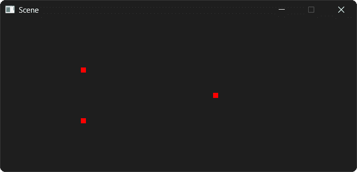
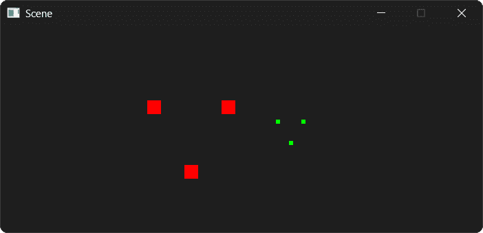
};Running our scene, we should now see our two triangles. Both are the same size in world space, but the red triangle is closer to the camera:
Complete Code
Here is the complete Triangle.h file, which contains the heart of our new 3D pipeline. The other files (main.cpp, Window.h, Scene.h) remain largely the same as the starting point.
Files
Summary
We have now implemented a complete 3D transformation pipeline! We've moved beyond hardcoded 2D offsets and embraced the standard mathematical model used by virtually all 3D game engines.
- View Matrix: We used
glm::lookAt(),glm::translate(), andglm::rotate()to create two different virtual camera systems, allowing us to move around the scene. - Projection Matrix: We used
glm::perspective()to create a 3D frustum, giving our scene depth and perspective. - Perspective Divide: We manually implemented the division by , converting our 4D clip-space coordinates into 3D normalized device coordinates (NDC).
- Viewport Transform: We mapped the -1 to 1 NDC range to the actual pixel dimensions of our SDL window, flipping the Y-axis to match screen coordinate conventions.
This pipeline - Model View Projection Perspective Divide Viewport - is the fundamental process of rasterization. While modern engines do most of this on the GPU, understanding the math on the CPU gives you total control over how your game world is presented.
Course Conclusion
Congratulations on completing this course! You've tackled window management, event handling, 2D rendering, a full entity-component system, game physics, and the complex mathematics of linear algebra with vectors and matrices.
This course has given you a toolkit and a solid foundation. The world of game development and real-time graphics is vast, and there are many paths you can explore from here. Here are some suggestions:
Hardware-Accelerated Graphics
We've stuck with software rendering techniques using C++ on this course, but offloading work the GPU is the next logical step. Learning a graphics API unlocks modern rendering techniques and massive performance gains.
SDL2 introduced a hardware-accelerated 2D rendering API, and SDL3 added the GPU API for 3D rendering.
You can also work with lower level APIs directly. OpenGL is the classic cross-platform graphics API. It has a wealth of tutorials and is the easiest API to learn.
Vulkan, DirectX 12, or Metal are the modern, low-level APIs that offer maximum control and performance. They are more complex but are the standard for high-end game development today.
Recommended Resources:
- LearnOpenGL is widely regarded as the best free resource for learning modern OpenGL from the ground up. The concepts you learned about the MVP matrix will map directly to what you do with shaders in OpenGL.
Advanced Game Architecture
Our entity-component system is a great start. To build larger, more complex games, you can explore the patterns and practices used by professional game engines.
Recommended Resources:
- Game Programming Patterns by Robert Nystrom is an essential, free online book that covers many architectural patterns.
- Game Engine Architecture by Jason Gregory is a comprehensive textbook that covers the design of every major engine subsystem in detail.
Use a Dedicated Physics Engine
We implemented basic physics, including forces, impulses, and collision response. For more complex simulations, a dedicated library is the way to go.
Recommended Resources:
- Box2D is the industry standard for 2D physics. It's a fantastic library for platformers, puzzle games, and anything requiring robust 2D collisions and physics.
- Bullet Physics or PhysX for 3D physics. These are powerful, open-source libraries that handle everything from simple rigid body dynamics to complex vehicle and cloth simulations.
Try a Full Game Engine
Now that you understand what's happening behind the curtain, you're in a perfect position to appreciate what a full game engine provides. Working with an engine like Unreal or Godot will allow you to build complex games much faster, as they handle rendering, physics, asset pipelines, and more for you.
Recommended Resources:
- Unreal Engine uses C++ and has a world-class rendering pipeline. The concepts you learned here will make understanding its architecture much easier.
- Godot Engine is a powerful open-source engine. While its primary language is GDScript, it has excellent C++ integration, allowing you to write high-performance game logic in C++.
Thank you for taking this journey. Take what you've learned here, pick a project that excites you, and start creating. Good luck!